Warning! Warning! Warning! Warning!
This mod has some risk. There is risk that you will damage the plastic case, lift off the solder points, slice your own arteries open and bleed out. I AM not responsible for any damage you may do to yourself or your flashback. This mod kit is designed to make modding the flashback a little easier, no mod kit or mod kit instructions can eliminate risk.
Warning! Warning! Warning! Warning!
Tools Required:
Small Phillips screwdriver. Sharp razor knife. Flush cut pliers. Needle nosed pliers. Epoxy glue (or whatever glue you choose).
Phase 1: Disassemble the Flashback.
Turn the unit over, there are 5 screws that need to be removed. One on each corner, and one in the center under the label. Set the screws aside. Be aware that the case screws are slightly larger than the pc board screws so you might keep them separate.
Once the screws are removed, gently lift the back of the case off. Be aware that the video cable intersects the bottom of the flashback. When I do the mods, I’ve found it easier to clip the 3 leads from the pc board. I clip them close to the pc board. Unscrew the cable retention screw and washer. Remove the cable and replace the retention screw and washer.
I completely remove the AV cable, you may choose not to. I’ve just found it a little cumbersome when I’m working with the pc board.
Remove the screws from the pc boards for the switches. There are several screws that mount the switches to the case. Remove the screws and lift the pc boards away from the case. Be aware that these switches are spring loaded. I’ve lost springs because they flew off never to be found again. Once the pc boards are lifted and the springs removed, remove the buttons themselves. Store all of these parts somewhere for re-assembly later.
Remove the numerous screws retaining the pc board to the case. These screws along with the switch pc board screws are slightly smaller than the screws used to hold the case together. You do not want to mix the screws, they will either damage the case, or never tighten properly.
Phase 2: Pre-Soldering the pc board.
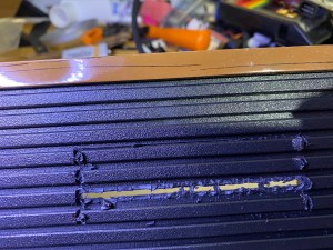
Remove the circuit board from the case. Flip the circuit board over and pre-tin the solder points, this is a good opportunity to identify every solder point and remove the component at J9. It will look like a surface mount diode, it’s not really a diode, it’s just a 0 ohm resistor. Remove J9 and pre-tin the solder points. Locate J3 and pre-tin that solder point also. You should have a total of 27 pre-tinned solder points. Twenty-four for the cartridge and 3 for the cartridge insertion sense switch. Six switch connections will be needed if you have an older style PCB with a black jumper wire. The following is an example of most of the contacts that need to be soldered. It is not a complete example, there are several different boards with slightly different pad locations.
On occasion there will be pads that look like they overlap each other. If you have a problem determining which pad goes with which number, please drop me an email and I will help get it sorted out.


Solder point pre-tinning.
I’ve found that on many of these units, the adhesive used to fix the copper pads onto the flashback motherboard has a tendency to be overly sensitive to heat. If heated for too long, or at too high a temperature they WILL lift off. It’s almost impossible to repair a lifted pad as often these pads are very close to the epoxy covered IC’s. I have done it and I will give some tips at the bottom of the document should you have this issue.
With the solder points of the board facing up, it’s time to pre-tin the solder pads. Pre-tinning will help keep the heat/time to a minimum and mitigate lift off of the contact pads. My personal preference is to run a fairly hot soldering iron and contact the pad only for about 1 second. Heating of the contacts seems to be cumulative. You will be touching the pads again when the wires are soldered on. Your mod kit will have the wire ends pre-tinned and cut to be very small. One issue I’ve had early on is insulation shrinkage due to heat. I’ve mitigated this by making the exposed wires very short.
Each solder pad needed for the mod has been kindly numbered thanks to Curt Vendel. Please see below for pictures of each board revision and where their solder points are. There can be a lot of variation in the solder point location. Pre-tin each pad and take a count to see that you’ve located all 24. Be aware, on the most common board available, solder points 18 and 23 are not located near the other contact points. Point 18 is far to the left, and point 23 is somewhat to the right. This is NOT true for all revisions. So use the reference pictures provided here if you need them.
You will need to identify your particular board revision in order to identify the correct solder points. Either way, you should pre-tin the solder points, this is also a good opportunity to identify all of the solder points. In all, there will 27 solder points.

STOP!!
DO NOT CONTINUE SOLDERING UNTIL YOU’VE COMPLETED THE PLASTIC WORK!!
Plastic Work:
Place the cutting template on the top of the top Flashback 2 molding:

Mark the inside paremeter of the rectangle. This template is designed to be slightly smaller than the actual size of the cartridge guide. This will allow some space to fit the guide more precisely.

Score the marked lines carefully. I usually score them several times, the goal isn’t to cut all the way through the plastic. A little later we will break the plastic and this score will stop the plastic from breaking to far outside of the template mark.

Carefully score the horizontal edges of the cartridge opening, this will make a weak point in the plastic so you can make a fairly clean break when the time comes, I usually push pretty hard to repeat this numerous times. The goal isn’t to go all the way through the plastic, but to make this line a very weak point:

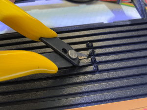
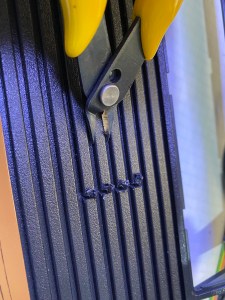
Using a pair of close side snips, with the beveled side ALWAYS facing inward, cut the vertical score marks, cut them as deeply as you can, this will keep the plastic from breaking past the left and right edges in an upcoming step:

Using the side snips, with the bevel side up, remove the ridge near the horizinal center of where the cart guide will go, remove this from the outside into the middle and repeat it for both left and right sides:
You should end up with something similar to this:
Flip the shell over at this point and remove some of the support material from the bottom of the shell:

TO BE CONTINUED….
Note: The cartridge slot MUST be inserted into the flashback case before soldering the leads to the circuit board. The cartridge insertion sensor switch(s) must NOT be installed into the cartridge guide until AFTER the guide has been installed. It’s NOT possible to install the guide with the switch(s) installed.
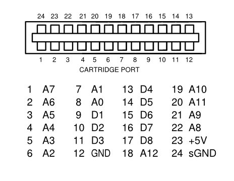
There should be a small piece of tape on wire number one of the cartridge connector. The wire is usually red (but don’t rely on that). Use the following diagram to confirm wire number 1. This diagram is from the point of view of looking directly into the spot where the cartridge would go in, with the label aiming to the top. I normally start with wire number 1, and work my way through 2,3,4,5 and so on, I also pull the wire away from the ribbon cable as I go, this stops mistakes when a wire gets skipped.
Once you’re to the end of the ribbon cable (wire 12), start with the wire above the wire just completed (wire 13), work your way back in the direction of wire number one. I’ve found it’s a little bit easier to move the cartridge guide up over the board so that the remaining contacts are exposed. A few of these contacts can be a challenge (21-22). You should end up on wire 24. Both wire 12 and wire 24 are ground wires and will end up soldered directly next to each other on the pc board.
Phase 3: Plastic work.
There are two phases in which the mistakes are most likely to be made. Soldering the leads to the pc board, and cutting the hole for the cartridge guide. Be careful, go slowly.
Using the hole cutting template from the mod kit, place it on top of the Flashback.

Score the raised edges with a razor knife (you’re not cutting, just marking the edge).
The template should fit snugly into the grooves on the sides and bottom of the top of the cover. Using a writing utensil, draw within the rectangular part of the template. You can ignore the small part of the hole that extends down towards the front of the flashback for now. This extrusion was for the version 2 mod, in version 3, there is no need to cut the extra notch out. I will be sending out an updated template without the extra notch. The cartridge guide includes an overhang to hide uneven cutting, It will hide a mistake of several millimeters. I consider this hole to be a “rough-in”, It will be just slightly smaller than the actual cartridge dimensions. The final cutting will be done with a razor knife.
If it makes it easier for you to work on this area, the control panels where the buttons are can be popped out and put back in later.
Once you’re done marking the hole to be cut, remove the template, it is no longer needed.
Using a very sharp razor knife, etch the plastic along the marked rectangular cutout. This part can be dangerous, be careful, and I’m not responsible if you cut something off of yourself, or end up with more holes than you were born with. Not my problem!
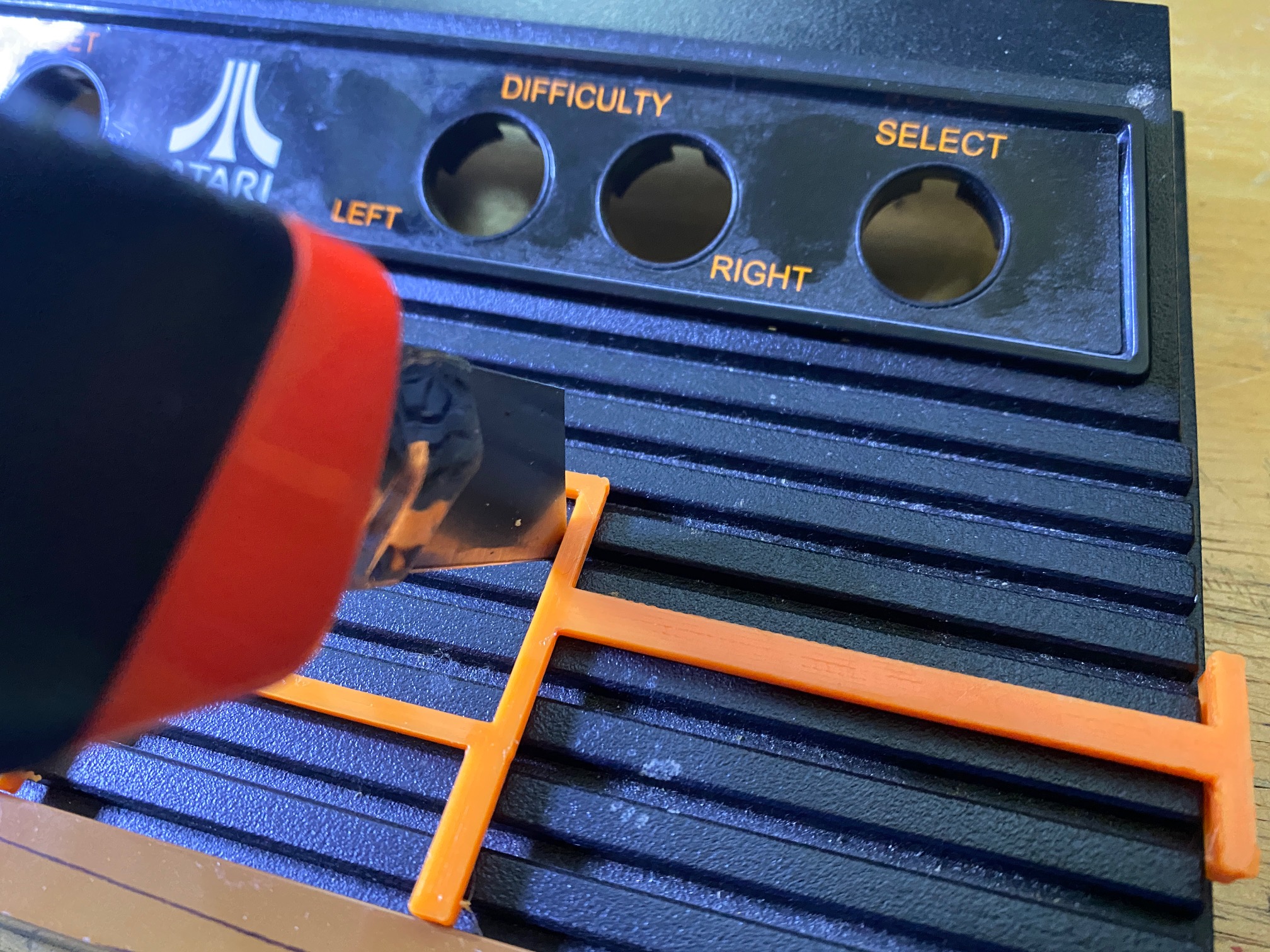
You will find etching down the horizontal parts fairly easy. Etch as close to the raised portion of the top as possible (see picture). I usually repeat this part of the process 5-10 times, going a little deeper each time. When the time comes, this will allow you to bend the plastic down and break it cleanly along the cut line. This only works for the horizontal cuts. I used flush cut pliers to cut the raised sections a few millimeters to the inside and away from the edge of the marked spot.
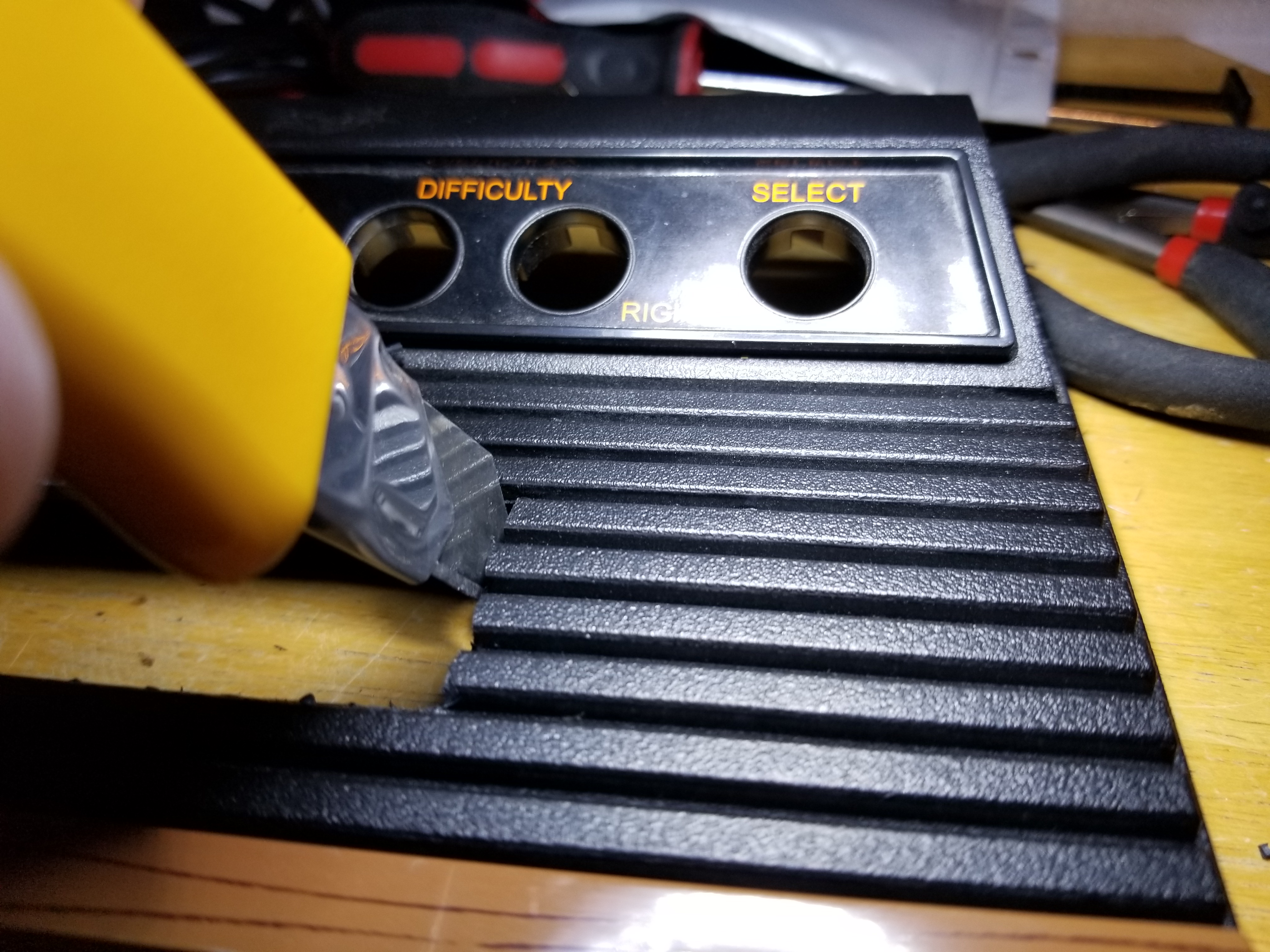
For the vertical cuts, I also use the razor knife to slice a line through the ridges. Try not to cut outside of the lines marked by the template. If you etch a line right up against the trough at a 45 degree angle, you can do it several times and when you cut the plastic out, it will create a fairly clean line. if you slip, the cartridge guide will hide some degree of mistake, but it’s not unlimited. I’ve found it beneficial to keep making these slices into the plastic several times and with increase pressure. The better you can make these cuts, the less likely the plastic will fracture and break in an unwanted location.
Now, take a pair of cutting pliers (I used flush cut pliers used for pc board work) to clip out the raised sections of the plastic within the rectangle. PLEASE be aware, the plastic is brittle, it WILL eject at high velocity. It could easily damage an eye. You should wear eye protection for this project. Keep working at this until most of the plastic is removed and you have a rough opening.
Board Revisions and their associated solder points:
Yellow circles are solder points for the cartridge. Red x’s and blue circles are solder points for the cartridge insertion switch.
Cartridge Mod Version 3 Color Coding:
This is from the perspective of facing the cart as if you were going to put a cart into it.
This is critical and where getting the wrong lead soldered to the wrong pad is the most common issue. Pay attention here:
From Left to Right:
Brown: 24 (Ground)
Red: 1
Orange: 23
Yellow:2
Green:22
Blue:3
Purple:21
Gray:4
White:20
Black:5
Brown:19
Red:6
Orange:18 <–May need an extension
Yellow:7
Green:17
Blue:8
Purple:16
Gray:9
White:15
Black:10
Brown:14
Red:11
Orange:13
Yellow:12
Revision B. Version 2
This board will need the extra length for connection 18. I will usually include some extra lead on 18 with tape on it. If your version of the board doesn’t need this extra length, just remove the tape and cut at the solder joint.

Revision B. Version 3

Updated 02/07/2022
